
LISP Add-Ons for 3D

This unofficial help page is about tools around Modeling, the core of SolidDesigner.
It is about lisp programs and add ons for:
- Modeling - creating parts (3D functions)
- Creating 2D Geometry / Construction Lines on Workplanes
- Handling of Workplanes
- Positioning, making multiple Copies / Instances
- Properties and Settings
- Structure Browser
- Machining Module - recognized features
- Face Parts, in-accurate Parts, Clouds of 3D-points
- Measure
- and a view more things ...
 Be aware the translation is still in progress. Many of the tools are still available in German only;
the tool itsef as well as the description. Monochrom screen shots will show you that the tool itself
is not available in your language yet. Volunteers are welcome.
Be aware the translation is still in progress. Many of the tools are still available in German only;
the tool itsef as well as the description. Monochrom screen shots will show you that the tool itself
is not available in your language yet. Volunteers are welcome.Subtopics of this page are:
- 01 Thread
- 02 Feathers / Rectangle feathers
- 03 color palette
- 04 Create Square and Round Pipes
- 05 Thread, Machining
- 06 Parts, Accuracy
- 07 Assembly, explode
- 08 Parts Color
- 10 Gd_vieleck.lsp / polygon
- 10 Hexagon / Polygons
- 11 Face parts, delete
- 12 Countersink / Cone cuts
- 13 Bore, negative
- 14 Parts, Mass
- 15 Part infos / os_teileinfo.lsp
- 15 Parts, Info
- 16 Curves and points / kurven_und_punkte.lsp
- 17 Objects counting
- 18 Line centroid
- 20 Structural browser, hide parts
- 21 Sco_rem_drawlist.lsp
- 22 Cross-section assembly
- 23 Shaft, stepped
- 25 Undercut
- 27 Contents ID
- 28 Positioning of cones and balls
- 29 Parts, Properties
- 30 More Object Properties in Structure Browser
- 31 Derivation, Layout
- 32 Del_undo.dll
- 34 Picture sequence
- 36 Create Helix
- 37 Groove lines
- 38 Structural browser, clean up
- 39 Parts, multiple copy
- 40 Exchange shared parts/assemblies by another one
- 41 Axes, distance measuring
- 42 Edge length
- 43 Analysis surfaces
- 44 Modeling a chain automatically
- 45 Wire <> Solid Part Conversion
- 46 Spiral Pattern with shared Parts
- 47 Create Workplane at Centroid
- 48 Place Machining features more convinient
- 49 Pattern of Construction Lines
- 50 Holes for Ejot and Helicoil
- 51 Bisecting Line
- 52 Save PKG with preview thumbnails
- 53 Relative Measure of 3D Points
- 54 Store Modelle as STEP or SAT
- 55 Convert 3D-coordinates in STEP
- 56 Create L-Profiles
- 57 Reverse display on/off
- 58 Text along Arc
- 59 Copies of contents Objects
- 60 Measture Angel of 3D Edges
- 61 Create drill tools
04 Create Square and Round Pipes △ ▽

- Thanks to unknown
- Discussion took place at user forum on on CAD.DE.
- File to download/load is Rohre_rund_und_eckig.lsp.
- Date created/updated is about October 2004.
Translated by Tom Kirkman.
The first version of this tool creates complete pipework in a simple way.
The user interface is easy to understand and it was enhanced to create rectangular pipes, too.
To create rectangular steel pipes according to DIN 59411 you might want to give os_st_rchtr_59411.lsp(Sep 2003) a try.
(undo :max_back 1)
05 Thread Dimension Table for Machining Module △ ▽

- Thanks to PeterO
- Discussion took place at user forum on on CAD.DE.
- File to download/load is machining14.lsp.
- Date created/updated is about June 2005.
This is an extension for the thread table of the Machining Module within SolidDesigner.
The file machining14.lsp
should be loaded from within
<custdir>/MachiningAdvisor/ma_customize file.
That way the command new measurements are available as soon as the module was started.
For the nostalgia users of 𝒮ℴ𝓁𝒾𝒹𝒹ℯ𝓈𝒾ℊ𝓃ℯ𝓇, a version for older guys is available as well: machining.lsp (Mai 2003 bis V13).
See also more information on CAD.DE
Machining Thread Settings
- Thanks to SReinbold
- Discussion took place at user forum on on CAD.DE.
- File to download/load is Machining_Anpassungen.zip.
- Date created/updated is about November 2010.
In further extension of the table is contained in Machining_Anpassungen_V17.zip
The contents of the zip file should be loaded from within
<custdir>/MachiningAdvisor/ma_customize file.
That way the command new measurements are available as soon as the module was started.
The contents of am_customize_machining can be loaded via <custdir>/Annotation/am_customize file
to adapt the representation of threads in the Annotation views.
For the nostalgia users of 𝒮ℴ𝓁𝒾𝒹𝒹ℯ𝓈𝒾ℊ𝓃ℯ𝓇, a version for older guys is available as well: Machining_Anpassungen.zip (Sep 2007).
08 Color Parts Randomly △ ▽

- Thanks to chris-as
- Discussion took place at user forum on on CAD.DE.
- File to download/load is Zufalls_Farbe.lsp.
- Date created/updated is about August 2007.
Enhanced by Schneewittchen and translated by der_Wolfgang.
Grey in grey is quite boring for whole assembly. But coloring each and every single part within (an imported) assembly is not a nice task. So by using Zufalls_Farbe.lsp (Random Color) every part within an assembly gets nearly another color randomly.

On the other side too colorful assemblies are not looking good. More tightly focused you can do the job using sd_teileumfaerben.lsp (part coloring) (Mar 2008).
13 Hilfsbolzen erzeugen △ ▽

- Thanks to misc
- Discussion took place at user forum on on CAD.DE.
- File to download/load is hilfsbolzen.zip.
- Date created/updated is about May 2008.
Manchmal ist es ganz hilfreich, sich einen Körper zu erstellen, der gewisse Funktionen übernehmen kann um danach verschmolzen oder wieder gelöscht zu werden.
Hilfsbolzen in beliebiger Postion
|
gebastelt von highway45 erweitert von MiBr Einige Bauteile haben nicht immer eine gerade Fläche oder Achse und können dann nur mit Hilfsmitteln positioniert werden. Oder manchmal muß sich ein Bauteil zur Wandlung in ein Exportformat im postiven Raum befinden, günstigerweise nah am Nullpunkt, oder jemand hat es schräg im Raum abgespeichert. Oder nur um etwas zu zeigen oder testen erzeugt man sich manchmal einen Dummy-Klotz. hilfsbolzen.zip (Mai 2008) In der neueren Version sind ein paar Optionen hinzugekommen. Mit ein paar Klicks kann damit ein Bolzen an einer beliebigen Stelle im Raum platziert werden. Nun können Bauteile in Achsrichtung des Bolzens ausgerichtet werden oder an seinen geraden Flächen. Oder ein Bauteil kann gemeinsam mit dem Hilfsbolzen bewegt werden. |
|

Rundstab und Vierkant
|
mit freundlicher Genehmigung von Adrian F.
Mit diesen beiden Tools können viereckige oder runde Klötze erzeugt werden. Es werden zylindrische und konische Bolzen erzeugt und Bolzen mit einer Spitze, die als Negativ für eine Bohrung gedacht sind. Eckige Klötze können quadratisch oder rechteckig sein, der Anfangspunkt kann mittig oder außen liegen. rundstab.lsp (Nov 2008). vierkant.lsp (Nov 2008). |
|


Negativ für eine Bohrung erstellen
|
mit freundlicher Genehmigung von Michael Müller
Dies ist ein Dialog zum Erstellen eines Bolzens (Negativbohrung) mit frei definierbarer Länge und Durchmesser. Am Ende wird eine Spitze mit frei definierbarem Spitzenwinkel angebracht. Es muss eine AE auf einer Fläche liegen bzw. überhaupt eine AE vorhanden sein. negativ-bohrung.lsp (Aug 2003). |
|


Kegelstumpf über zwei Durchmesser erstellen
|
mit freundlicher Genehmigung von Michael Müller
Manchmal werden Formschrägen nicht über Winkel definiert, sondern im Toleranzfeld des Durchmessers. konischer-zapfen.lsp (Mai 2008) kann ein Hilfskörper erzeugt werden, der dann nur noch an der richtigen Stelle positioniert werden muß. Das konisch geformte Loch wird dann mit "Subtrahieren" erzeugt. Oder ein Dom mit "Vereinen". |
|


14 Thicken Menu △ ▽

- With friendly greetings from CoCreate.
- This is a build in goody of SolidDesigner.
The build in goody (load "cv3d_thicken")
can entered in the command line or added to sd_customize file makes a solid part from 3D wire lines.
A surfacing license is required
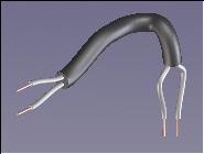
Without taking work planes can be created cables or hoses or tubes.
Some information about Surfacing functions without the need for a license can be found in Instructions.
25 Freistiche an Wellen △ ▽

- Thanks to PeterO
- Discussion took place at user forum on on CAD.DE.
- File to download/load is gdm_m1_freistich.zip.
- Date created/updated is about May 2008.
Dieses Programm erzeugt an einer kreisförmigen Kante einen normgerechten Freistich.
Es ist eine Tabelle enthalten mit Auswahl der verschiedenen Formen E, F G und H.
Zur Beschreibung der Abmessungen wird ein Vorschaubild angezeigt.

28 Positioning of cones and balls △ ▽

- Thanks to Walter Geppert
- Discussion took place at user forum on on CAD.DE.
- File to download/load is kegelpos_v2.lsp.
- Date created/updated is about May 2004.
Translated byTom Kirkman.
This tool is able to move cones or balls directly to other cone forms.
Useful for instance to place a valve sealing on its aperture.
30 More Object Properties in Structure Browser △ ▽

- Thanks to holt
- Discussion took place at user forum on on CAD.DE.
- File to download/load is custom_browser_views.lsp.
- Date created/updated is about May 2007.
Starting with SolidDesigner Version 14 the structure browser can offer different kind of views. Those view can be user customized (with the help of some lines of lisp). That way a view with some more columns can be created displaying more properties of the objects displayed in the structure browser.
By loading the attached file a new view will be added (visible at the upper right corner of the structure browser. In the new view there are new columns for density, geometry resolution and type of part (solid/face/wire-part). That way you get a better overview and the values can be edited as well.
Be aware that inquiring more information of each and every object might slow down the performance of the structure browser since the data is retrieved on the fly (even when CoCreate implemented some caching algorithm here as well).
Its a good idea to switch back to the "Standard" view for normal working.
36 Create Helix △ ▽

- Thanks to Thömu
- Discussion took place at user forum on on CAD.DE.
- File to download/load is helix.xls.
- Date created/updated is about June 2009.
It is almost impossible with build in functionality to create a rounded shaped spiral.
However, with the help of Excel the calculation of 3D points is feasible. Then these coordinates can be written to a recorder file to generate a 3D-curve.
The Excel calculation does not create the syntax for the 3D points.
Therefore the recorder file need to be adjusted to make the points look like 0.00,0.00,0.00 (without any blanks etc.).
It is higly recommended to edit the recorder file using Notepad++.

As an example here is an already prepared recorder file: helix.rec
In the Excel file the calculation of a workplane is also included. With the help of the geometry on the workplane and the command profile along curve a solid model of a spiral can be created as well. The workplanes origin is in standard direction at a point of the helix curve.
Last but not least: since version 15.5 a 3D-curve can also be created with the help of an entered function.
39 Duplicate Parts with Free Positioning △ ▽

- Thanks to Walter Geppert
- Discussion took place at user forum on on CAD.DE.
- File to download/load is parts_multiple_V14.lsp.
- Date created/updated is about January 2007.
Translated byTom Kirkman.

Selection can be done with multiple parts already. Also assemblies are possible to select.
The new Positions are totally free, also the direction at the destination position can be defined.
That is quite good tool, e.g. to spread around already existing standard parts to additional positions. Because of the capability to select multiple parts or assemblies as source also complete screw connections can be multiplied.
This tool parts_multiple_V14.lsp is made for V14. Older Version can be found at the German page.
40 Exchange shared parts/assemblies by another one △ ▽

- Thanks to unknown
- Discussion took place at user forum on on CAD.DE.
- File to download/load is gb_ex_pa.lsp.
- Date created/updated is about December 2006.
Loading the tool gb_ex_pa.lsp (Dez 2006 V11 - V14) user can replace existing shared parts by another part, by keeping the position and the location in the assembly / part structure.
This will save a lot of time because there is no need to place every single instance. Use it when exchanging shared parts which exist in a higher number, but have to be changed later.
- load the new part and place it where you want, or use an existing one
- start the tool via toolbox
- select the new part as "Source"
- select an old one as "destination"
- optionally select more destination parts, using the select UI in addition, these parts have to be a real share of the first destination part
- press ok and all destination parts will be replaced by an instance of the source part
44 Modeling a chain automatically △ ▽

- Thanks to Urs Thali
- Discussion took place at user forum on on CAD.DE.
- File to download/load is kette.lsp.
- Date created/updated is about August 2007.
Translated and with some help and ideas of der_Wolfgang.
With the program kette.lsp a normal link chain will be created.

Simply play with the parameters and the chain will be created as an assembly group with shared links in it.
For the nostalgia users of 𝒮ℴ𝓁𝒾𝒹𝒹ℯ𝓈𝒾ℊ𝓃ℯ𝓇, a version for older guys: kette_v11.lsp
45 Holes for Ejot and Helicoil △ ▽

- Thanks to PeterO
- Discussion took place at user forum on on CAD.DE.
- File to download/load is gdm_m1_ejot_delta_pt_bohrung.zip.
- Date created/updated is about November 2005.
In 3D we can specify a part to be half transparent, or even more to use a wire part to get an impression of a part without to see it completely / to look through. In Annotation views this is difficult to realize and the only known workaround is to use two views and place them accordingly covering each other. But it is hard to maintain the real position and thinking about dependent views these difficult steps have be done again. A wire part would help, but this is not handled by the view calculation.
Therefore the idea to have a solid part representing a (former) wire part was born: With the program sd_wire2solid.lsp a wire part can be converted to a solid part using a certain wire thickness. And the conversion can be reverted, too.
After doing so the converted part might be re added to the view(s) again, to make it visible in Annotation after the next view update.
- All database infos, the model name, the sys id are unchanged at the part converted.
- The original geometry can be kept optionally (in a container). Doing so the reverse conversion is possible.
- Not to influence the mass of the owning assembly the density is set to a minimal value.
- The converted part is marked as pressfit part, because the measurement is slightly bigger giving the wires a certain thickness.
- There are known problems if the wires do not belong to a single 'wire cluster'. TIP: remove circles of holes etc., before converting the part. Otherwise the part will collapse into several parts during conversion and geometry can not be united again.
46 Spiral Pattern with shared Parts △ ▽

- Thanks to Schneewittchen
- Discussion took place at user forum on on CAD.DE.
- File to download/load is wendel.lsp.
- Date created/updated is about November 2007.
Copy/Share parts in linear direction or as radial pattern are known standard commands. Using the tool wendel.lsp will add another dimension for multiple copy / share.
Using a radial pattern spiral staircases are created. With linear duplication the parts are just turning around one axis.

47 Create Workplane at Centroid △ ▽

- Thanks to MC
- Discussion took place at user forum on on CAD.DE.
- File to download/load is ae_in_schwerpunkt.lsp.
- Date created/updated is about December 2005.
With the help of the tool ae_in_schwerpunkt.lsp the coordinate system of a workplane can be made aligned to a parts centroid. Parts (multiple selection) as well as assemblies are allowed to select.

48 Place Machining features more convenient △ ▽

- Thanks to der_Wolfgang
- Discussion took place at user forum on on CAD.DE.
- File to download/load is osd_ma_context_menu.lsp.
- Date created/updated is about March 2008.
When all parameters of a Machining (Advisor) feature are specified it would be more handy and would save time when there's not the need to move the mouse pointer position from the view port to the menu and back for each and every new feature which should be placed. Also other options should avoid long mouse travelings.

The Tool osd_ma_context_menu.lsp adds a right mouse button context menu to every (known) Machining (Advisor) feature. Right in the view port you can trigger specification of new direction, center point, face, and you can execute the 'Next' action.
osd_ma_context_menu.lsp
should be loaded be loaded from within
<custdir>/MachiningAdvisor/ma_customize file.
That way the command specific context menus are available as soon as the module was started.
50 Holes for Ejot and Helicoil △ ▽

- Thanks to PeterO
- Discussion took place at user forum on on CAD.DE.
- File to download/load is gdm_m1_ejot_delta_pt_bohrung.zip.
- Date created/updated is about November 2005.

With these both lisp programs holes can be provided in downpour parts, suitably for the plastic screws by Ejot delta PT and for the thread applications of Helicoil plus.
Both tools have nice preview images showing the definitions of the dimensions.
Pressing the yellow question mark or the button 'data sheet' will display specific help information.
Because of the help files and the images the downloads will be handled via compressed files:
- gdm_m1_ejot_delta_pt_bohrung.zip (Nov 2005)
- gdm_m1_helicoil.zip (Feb 2007)
61 Create drill tools △ ▽

- Thanks to taino
- Discussion took place at user forum on on CAD.DE.
- File to download/load is tp_bohrer_v19.lsp.
- Date created/updated is about February 2015.
Using this tool a very detailed HSS spiral drill will be created.
The dimensions need to be added manually.
Here are some examples (for metric drills):
| Ø | length | shaft |
| 1 | 34 | 12 |
| 2 | 49 | 24 |
| 2,4 | 57 | 30 |
| 3 | 61 | 33 |
| 3,2 | 65 | 36 |
| 4 | 75 | 43 |
| 4,8 | 86 | 52 |
| 5 | 86 | 52 |
| 5,6 | 93 | 57 |
| 6 | 93 | 57 |
| 6,4 | 101 | 63 |
| 7 | 109 | 75 |
| 7,2 | 109 | 75 |
| 8 | 117 | 75 |
| 9 | 125 | 81 |
| 10 | 133 | 87 |

If you are a rather old guy, or if your system is very outdated you might need to load tp_bohrer.lsp (up to V18) for your very early days version of SolidDesigner.
The English pages of osd.cad.de are currently (=Dec2017) under some re-constructions. Topics I try to attack:
- DONE On the fly translation of German-only pages, based on good progress of those translators.
- ongoing More Mobil friendly UI (at least friendly, may be not full responsive).
- DONE SEO related issues
- DONE(17/12) + ongoing check for HTML compliance (use of tidy / W3C Markup Validation Service)
- OPEN Split of some lengthy files into some sub pages (idea: about 10 chapters per page)
- ... feel free to drop me a note via the forum's private message functionality


