
LISP Add-Ons for Annotation (2D)

This unofficial help page is about tools around Annotation, the 2D documentation part of SolidDesigner. The Annotation module was added late in 1997, with version 5.1 of SolidDesigner. The former drawing process was based on 'layout' and using ME10 (today's name 'PTC Elements Direct/Drafting') to annotate the drawing by adding dimensions and texts etc. The Annotations 2D view port for the drawing area is still provided by a ME10 process running in background and totally controlled by the SolidDesigner functionality.
- To download a tool just click with your right mouse button and choose save link target as.
- To load a LISP file, just drag and drop it from your file manager into a running SolidDesigner. Other possibilities for loading are described in the instructions section.
- For permanent use it is recommended to load the tools from within sd_customize file located in your user customize directory of the SolidDesigner version in use.
- There is no guarantee for proper functionality!
- If known the date of making a tool public is written after the (lisp) file to be downloaded. The date of publishing might also give a hint for the (oldest) SolidDesigner version it is working.
 Be aware the translation is still in progress. Most of the tools are still available in German only;
the tool itsef as well as the description. Monochrom screen shots will show you that the tool itself
is not available in your language yet. Volunteers are welcome.
Be aware the translation is still in progress. Most of the tools are still available in German only;
the tool itsef as well as the description. Monochrom screen shots will show you that the tool itself
is not available in your language yet. Volunteers are welcome.Subtopics of this page are:
- 01 Position numbers
- 02 Mirror View/Sketch
- 03 Sectioning, protect
- 04 Hatch, random
- 05 View user-defined direction
- 06 Sheet Delete, inclusive views
- 07 Create Leader Line
- 08 Explosion drawing, formations
- 09 Parts, Color in 2D // Teile im Annotation umfärben
- 11 Break multiple dimension lines
- 12 Show 3D owner // 3D-Besitzer anzeigen lassen
- 14 Dimension Hole cirlce
- 15 Arrange Sheets next to next
- 16 Convert Text to Geometry / Arrange Text Circular
- 17 Behavior of Cutaways in Section Views (V11-14)
- 18 Save a single View to disk
- 19 Table of coordinates / drill table
- 20 Hide Elements
- 21 Measure Properties of 3D Objects
- 22 Adjust Dimensions Texts
- 23 Change default of BOM Leaderlines
- 24 Revisions CloudNew
01 Position Numbers △ ▽

- Thanks to Walter Geppert
- Discussion took place at user forum on on CAD.DE.
- File to download/load is am_posnum1.lsp.
- Date created/updated is about November 2002.
With the tool am_posnum1.lsp it is possible to set position numbers, assign them to an owner, unassign them and delete them. The numbers are continuously and some other properties are changeable, too (size, distance). With the most recent version of the tool also the font can be set.
Using SolidDesigner version 14++ there are problems reported which are in work by the forums member. See the postings over there.
02 Mirror View/Sketch △ ▽

- Thanks to Walter Geppert
- Discussion took place at user forum on on CAD.DE.
- File to download/load is annotation_spiegeln.lsp.
- Date created/updated is about March 2008.
Enhanced to mirror sketches and more feedback byder_Wolfgang.
With the Tool annotation_spiegeln.lsp (Aug 2003 + Mar 2008) a view or a sketch can be mirrored in Annotation.
If you have mirrored parts, and you are going to continue on one side and don't want to create the 2nd drawing from scratch it will save you some time. First the views are mirrored, then the view set will be connected to the mirrored part, using Migration Tools.Attention: some dimensions, texts or symbols might loose their references. But not all.
03 Sectioning, protect assemblies △ ▽

- Thanks to Walter Geppert
- Discussion took place at user forum on on CAD.DE.
- File to download/load is am_assy_protect_14.lsp.
- Date created/updated is about August 2006.
Some Version of SolidDesigner did not allow to secure several parts against sectioning in Annotation views in a single step. Using am_assy_protect.lsp (Aug 2003) does work around the missing multiple selection issue. That way complete assemblies can be handled as well.
If you are a rather old guy, or if your system is very outdated you might need to load am_assy_protect.lsp (Aug 2003) for you very early days version of SolidDesigner.
04 Hatch, random pattern △ ▽

- Thanks to Ralf Albrecht
- More information here.
- File to download/load is Zufalls_Schraffur.lsp.
- Date created/updated is about October 2003.
The provided tool does change an existing hatch using a random distance (between minimal and maximal value) and changes the color as well.
- When selecting multiple hatches you need to use the "Next" button.
- Selecting just one hatch the changes are directly attached, so you can watch how it will look like
If you do not like the hard coded default values, feel free to change the values in line 11 .. 13.
05 View in any Direction △ ▽

- Thanks to Walter Geppert
- Discussion took place at user forum on on CAD.DE.
- File to download/load is am_direction.lsp.
- Date created/updated is about October 2003.
Using SolidDesigner versions 15.00 and newer do not need this add-on any more.
Walter have been looking for a way to create a view X in Annotation using any kind of direction.
Remark: Der_Wolfgang is not sure about why not using a general view for that?
Netter Nebeneffekt: Probleme mit nicht angezeigten Teilen in der Ableitung kennt das Progi anscheinend nicht, d.h. es erzwingt regelrecht eine Ansicht.
06 Sheet Delete, inclusive views △ ▽

- Thanks to Walter Geppert
- Discussion took place at user forum on on CAD.DE.
- File to download/load is am_sheet_del.lsp.
- Date created/updated is about November 2003.
Using SolidDesigner versions 15.00 and newer do not need this add-on any more.
With this tool it is possible to delete a complete sheet with all it's contents. Annotation does not allow to delete a sheet containing views. So you first have to delete every view (and confirm the deletion in addition), before you can delete the sheet itself.
This is quite annoying, specially when you are reusing existing drawings. With this tool all views are deleted before the sheet gets deleted.
07 Create Leader Line △ ▽

- With friendly greetings from CoCreate.
- This is a build in goody of SolidDesigner.
Sometimes you are running into the situation that you are not allowed to create a reference line. It it not possible to create a reference line from one view pointing into another for example. Or create those lines on sheet level.
For that situation you can use a Leader Line. To activate enter (load "am_leader") and you will find a new button in your tool box.
Leader lines and reference lines are very similar. Creation is nearly the same and properties (color etc.) are identical and controlled by the same actions.
BUT! Leader lines are NOT associative! So, when the element the Leader Line is visually pointing to is moved (e.g. by updating the view) the arrow stays at the position where it is. This might lead to misunderstandings later. A real reference line will move it's arrow accordingly. So: as far as possible real reference lines are to be preferred.
08 Explosion drawing, formations △ ▽

- With friendly greetings from CoCreate.
- This is a build in goody of SolidDesigner.
- Date created/updated is about February 2004.
Using SolidDesigner versions 14.00 and newer do not need this goody any more. The functionality 'Configuration', available in the 2nd Part & Assembly menu, is a complete replacement for the combination of sd_form and am_form.
In version 14.50 and newer you will use configurations! The old formations can/have be converted to a configuration.
This is a build in goody of SolidDesigner up to version 13.xx.
To create explosion drawings from your assembly you need to use the tools sd_form and am_form. sd_form creates the 'exploded' situation, where am_form is using the already defined formation for a new Annotation view. The usage of sd_form is explained in another document [DE].
To activate enter (load "am_form") and you will find a new button in your tool box.
There are German instructions available, how to use the formations.
11 Break multiple dimension lines △ ▽

- Thanks to RainerH
- Discussion took place at user forum on on CAD.DE.
- File to download/load is am_masslinienunterbrechung.zip.
- Date created/updated is about February 2004.
If you run into the situation that there several dimension lines placed on each other and in addition not of type 'Dimension long' it is cumbersome that all the dimension lines can not be broken in one step.
Here comes Rainer's tool into play.
The zip file contains a LISP and a ME10 macro file. To load the macro file correctly line 3 in the lsp file need to be adjusted.
There is no entry in the tool box. You can invoke the command in the command line via:
am-masslinienunterbrechung
12 Show 3D Owner △ ▽

- Thanks to Walter Geppert
- Discussion took place at user forum on on CAD.DE.
- File to download/load is am_show_owner.lsp.
- Date created/updated is about February 2004.
Show the 3D owner of selected geometry in of every part in Annotation views.
Remark: In drawings with several 3D-owners and/or with sheet metal parts with flat view the result might not be correct.
In more recent versions of SolidDesigner this functionality is build in and does not have any restrictions.
14 Dimension Pitch Circle △ ▽

- Thanks to RainerH
- Discussion took place at user forum on on CAD.DE.
- File to download/load is teilkreisgeo_16.lsp.
- Date created/updated is about April 2005 / Nov 2025.
With this Lisp we can very simply dimension pitch circles or flanges in Annotation Module.
For rather old versions of SolidDesigner compliant version is available as well: teilkreisgeo.lsp (April 2005 bis V14 + Nov2025). This Version is only available with German User Interface.
15 Arrange Sheets next to next △ ▽

- With friendly greetings from CoCreate.
- This is a build in goody of SolidDesigner.
In Annotation there is only less control on the absolute position of the sheets and their position to each other. Only when using external MI viewers or creating a PDF file or something similar you might see the effect that the sheets do cover each other or are spread around.
The command AM_ARRANGE_SHEETS rearranges the sheets of a drawing. This command can be called before a multi-sheet drawing is stored. The result is that single sheets are stored next to each other in the MI-file and do not cover another one.
To activate enter (load "am_arr_sheets") and you will find a new button in your tool box. Just press this button before saving/exporting the drawing.
In up-to-date versions of SolidDesigner the sheets are arranged in a square and in ascending order.
16 Convert Text to Geometry / Arrange Text Circular △ ▽

- With friendly greetings from CoCreate.
- This is a build in goody of SolidDesigner.
Two goodies, which might also be helpful in combination:
Enter (load "am_text_arc") and you will
find a new button in your tool box named "Text on Arc".
Every single character of the entered text will be placed with a different angle
aligned to an selected or virtual arc.

Enter (load "am_text2geo") and you will
find a new button in your tool box named "AM Text -> Geo".
With this tool text will be converted into geometry. The result in similar
to the 'text to geometry' command in modeling. But in Annotation there are much
more possibilities to to define the outlook of the text before making geometry out of it.
Later that geometry can be copied into a work plane, e.g. to mill your company logo
into your parts.
Remark: The round curves are not converted to splines, a polyline is used.
If used frequently, both tools can be loaded via am_customize, of course.
17 Behavior of Cutaways in Section Views △ ▽

- Thanks to christian137
- Discussion took place at user forum on on CAD.DE.
- File to download/load is am_vorgaben.lsp.
- Date created/updated is about November 2006.
There will be a new entry in the toolbox to control the behavior of cutaways in other (dependent) section views.
If a view contains a cutaway this one will not be used when creating a section view of that view. With the help of this tool the cutaway can be transferred to the section view.
Remark: one problem exist: if loading the drawing later on (or by another user) this tool need to be loaded to get the wanted behavior on view updates.
Using SolidDesigner version 15.00 and newer do not need this add-on any more.
18 Save Views/Sketches to Disk △ ▽

- Thanks to der_Wolfgang
- Discussion took place at user forum on on CAD.DE.
- File to download/load is save_ansicht_m.lsp.
- Date created/updated is about October 2007.
Translated and enhanced by der_Wolfgang.
With the program save_ansicht.lsp (??? 200X + Oct 2007) a single view can be saved to the file system in different file formats. After selecting a view (flat views are working, too) the MI data of the view are exported as MI, DXF, DWG, or SVG (in newer versions). Then you can hand over the data to the next post process.
Based on a new discussion in the forum an extended version was created which can handle sketches in addition as well as selecting multiple items. Use this version save_ansicht_m.lsp with multiple selection.
An alternative are the migration tools available in the Annotation module. Over there a view can be converted to a sketch, and then saved as sketch using standard save process.
Last but not least a simple approach made by der_Wolfgang: Move the view to a new empty sheet, select a 'none' frame and export the sheet as MI/DXF/DWG... to the file system.
Well, method 2 and 3 are destructive, so you have to reload the unchanged drawing afterwards again (or use UNDO in version 15.00++). The additional tool does not modify the drawing at all.
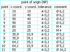
19 Table of coordinates / drill table △ ▽

- Thanks to schneewittchen
- Discussion took place at user forum on on CAD.DE.
- File to download/load is koordinatentabelle.lsp.
- Date created/updated is about October 2007.
Translated and user guidance added by der_Wolfgang.
To increase the overview on drawings some people like to use a table for a couple of measurements and fill in the coordinates and may be other information, too.
Using koordinatentabelle.lsp (Sep 2007) such a kind of table can be created and filled easily.
It creates the position numbers automatically together with a kind of leader line. The columns with the coordinates are also filled without additional interaction. Columns like tolerance or comment have be filled manually or can be deleted.
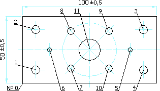
The created leader lines are NOT associative! So, when the element the Leader Line is visually pointing to is moved (e.g. by updating the view) the arrow stays at the position where it is. This might lead to misunderstandings later.
20 Hide Elements △ ▽

- Thanks to Walter Geppert
- Discussion took place at user forum on on CAD.DE.
- File to download/load is am_hide_elements.lsp.
- Date created/updated is about December 2007.
Sometimes designer would like to hand over a drawing without revealing all information. Now one can extinguish these things and then send the drawing to your subcontractor / customer etc.
To make the function convenient for the CAD user some information are attached to the elements to be hidden. That way the 'hiding' can be switched on/off as needed.
Any elements of a drawing can be hidden, as for example mass, geometry, frames, texts, etc.


Sometimes something should be faded out to get an better overview. The second tool fades out by an easy clicking components, views or sketches or shows them only as a frame:
The tool's file to load is am_hide_parts.lsp (Jan 2007)

21 Model Properties for Drawing △ ▽

- Thanks to holt
- Discussion took place at user forum on on CAD.DE.
- File to download/load is AM_TeilemasseAufBlatt.lsp.
- Date created/updated is about July 2007.
Several companies are using internal standard to document the mass or volume of the 3D Model in the drawing.
Those 3D Model properties can be measured in 3D and using copy and paste they can be added as text in Annotation.
Lazy contructors / designer can use the tool AM_TeilemasseAufBlatt to do the task in a comfortable way:
The owner of the view will be determined and the results of different measurements will be placed in the drawing.
A similar (but very basic) functionality is mentioned in 'Anleitungen 02'. Mass and volume of the current part is measured on just a click, after you have created an available command with the push-actions like those:
- cancel_all get_vol_prop :for_part :Part :current :mass
- cancel_all get_vol_prop :for_part :Part :current :volume
- cancel_all get_vol_prop :mass :for_part :Part
- cancel_all get_vol_prop :volume:for_part :Part
23 Change default of BOM Leaderlines △ ▽

- Thanks to SReinbold
- Discussion took place at user forum on on CAD.DE.
- File to download/load is bom_create_flag_refline.m.
- Date created/updated is about November 2008.
In Annotation there is always only one type of reference lines for BOM Flags.
If there should be different kind of reference lines one need to change the defaults temporarily or change the lines afterwards.
This modified macro bom_create_flag_refline.m is doing the changes upfront.
The values in the mentioned line numbers can be adapted:
- line 20: Dot_diameter 2.5
- size of the end of the leader, e.g. 1.5 instead of 2.5
- line 46: LEADER_ARROW Dot_diameter DOT_TYPE END
- e.g. ARROW_TYPE, SLASH_TYPE, TRIANGLE_TYPE, JIS_TYPE, NONE instead of DOT_TYPE
- line 58: RTL_COLOR YELLOW END
- e.g.GREEN, RED, BLUE, WHITE, CYAN instead of YELLOW
The macro will be loaded via
- (oli::sd-execute-annotator-command :cmd (format nil "input '~A/bom_create_flag_refline.m' " *anno-patch-dir*))
- (UNIVERSAL_LOAD :FILE "C:/User/Lisp/bom_create_flag_refline.m")
- via drag'n drop
24 Revisions Cloud △ ▽

- Thanks to taino
- Discussion took place at user forum on on CAD.DE.
- File to download/load is tp_rev_wolke.lsp.
- Date created/updated is about November 2017.
In some companies it is standard that changes are marked with a kind of cloud on the drawing. Those are called "Revision Clouds"
With the tool tp_rev_wolke.lsp (Nov 2017) it is possible to create such a cloud quickly.

Similar as drawing a (closed) spline with just a bunch of points to define you can create a cloud now defining points counterclockwise.
The English pages of osd.cad.de are currently (=Dec2017) under some re-constructions. Topics I try to attack:
- DONE On the fly translation of German-only pages, based on good progress of those translators.
- ongoing More Mobil friendly UI (at least friendly, may be not full responsive).
- DONE SEO related issues
- DONE(17/12) + ongoing check for HTML compliance (use of tidy / W3C Markup Validation Service)
- OPEN Split of some lengthy files into some sub pages (idea: about 10 chapters per page)
- ... feel free to drop me a note via the forum's private message functionality


