
Tips and Tricks

No guarantee for function and correctness !
Please consider that some commands and paths could be named different according to the software's version.
(If known the date of making a tool public is written after the file to be downloaded. The date of publishing might also give a hint for the SolidDesigner version it is working.)>
Subtopics of this page are:
Window (surface)
- 05 Save / print structure browser or BOM
- 06 Selection without selection menu
- 08 (Annotation) delete drawing
- 11 Moving symbols on icon bar without customize...
- 13 Seek and show the active part in big assemblies
- 22 Switch between drawing sheets
Lists (tabels/overviews)
- 01 Keyboard and mouse shortcuts
- 02 Symbols in structure and drawing browser
- 03 F-buttons as xls-download
- 04 Confidential commands, not very secret
Functions (modeling)
- 18 Repair damaged thread
- 19 SolidLibrary threat changing to machining part
- 23 Locked objects getting free again
Application (system)
- 07 SolidDesigner has stopped
- 09 Empty the UNDO buffer
- 10 Saving... by standing system
- 12 Copy_to_clipboard and paste_from_clipboard
- 14 Set the user interface back to default
- 15 application modules starting automatically
- 16 Show memory for SolidDesigner
- 17 Change memory for SolidDesigner
- 20 Annotation - Update on another PC
- 21 Printer clipboard in ME10
99 △ ▽

- Thanks to der_Wolfgang
- Discussion took place at user forum on on CAD.DE.
- File to download/load is dummy.lsp.
Keyboard and mouse shortcuts
All the default keys and shortcuts in SolidDesigner as pdf to download: Tasten_V14.en.pdf (Dez 2006)
Also available at CoCreate.
Symbols in structure and drawing browser
All the symbols you can find in the browsers to download: Strukturliste.en.pdf (Mai 2003)
F-buttons as xls-download
The twelve F-buttons to download in Excel: F-Tasten.xls (Mai 2003) can be printed on transparent paper and glued onto the keyboard.
How to define the keys by yourself is to find in user_man.html in the SolidDesigner installation path or in the online-help under "keyboard".
The customizing is placed in the file corp_keys (make safety copy before).
Confidential commands, not very secret
In forums sometimes turn up a few helpful strings.
Some of them do not work in all versions of SolidDesigner and they are only partially documented in the online-help.
To activate write the code into the input-line or into the customize-file or put it on a button.
Generally the same proceeding like loading a lisp, described in Tutorials.
Save / print structure browser or BOM
In the window of the structure browser:
- Right mouse click
- Actions
- Expand or reduce all
- Actions
- Write tree
- Save e.g. as tree.xls or tree.txt or tree.csv (don't forget the extension .xls oder .txt oder .csv)
- Open / print / change the list in Excel oder a text editor.
You get additional informations (name, path, model name, volumen, density, weight) after loading the tool sd_str_br_print_name.lsp(Sept2007 from Wolfgang).
Save other lists
There are several types of lists in Annotation.
For example the bill of materials created by the BOM function.
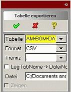
For saving it, the goodie (load "table_export_dia") has to be loaded to get the new entry "Export Table" in the toolbox.
To save the bill of materials the following steps are necessary:
- Load 3D-model and 2D drawing
- BOM - ScanModel - Manage - numbering (until here the normal handling for BOM tables)
- Activate "Export Table" in the toolbox
- Choose AM-BOM-DATA-LTAB (the other entries are for other types of lists)
- Chose format (HTML oder CSV for Excel)
- Press OK (at "file" the path is shown where the list will be saved)
Selection without selection menu
To choose several elements at one time it is not always necessary to activate the menu "selection list".
By holding the SHIFT-button + Left mouse-key several elements can be taken into a list.
Close the list with SHIFT + Middle mouse-key.
Is one Element to much in the list, during the choosing it can be removed with SHIFT-button and double clicking the Left mouse-key.
 Because I am not able to handle this, I made me the two buttons "start selection" and "end selection" in the menu line.
SolidDesigner has stopped

- Press key combination Ctrl - Alt - Del
- Activate Windows Task-Manager
- Tab prozesses
• At SolidDesigner.exe remind the PID number(important if several SolidDesigner are startet on the computer)
- Windows Start
- Execute...
• Put in cmd to open a DOS window
Go to the SolidDesigner folder with
cd \prog*\co*\osd*\ <+
Following command:
sdkill<blank>-8<blank><PID number><+
in this example sdkill -8 3636
 sdkill -8 only ends the actual command
sdkill -9 ends the SolidDesigner complete.
More simple is it to lay a connection to the file sdkill.exe into the Windows start menu.
Other possibility
end SolidDesigner directly with the Windows Taskmanager:- Press key combination Ctrl - Alt - Del
- Activate Windows Task-Manager
- Tab prozesses
- Mark SolidDesigner.exe and press "end process"
• Mark Annotator.exe and press "end process" (Right click on SolidDesigner.exe and then "end process tree" ends Annotation too.
One more tool
sourceThis program sd_toys10.zip unzip to a position outside the SolidDesigner installation files.
Then you get with sd_proc.exe an assistant to close SolidDesigner completely or to close only the actual calculation.
Note:
"The program stopped" usually has some reasons. Think about what could caused this problem. Perhaps the system is still working on an big operation. Or the hardware could be dimensioned to small for some operations.
(Annotation) delete drawing
Sometimes after deleting a drawing several informations keep staying on the screen or in background, but the button is not active any more.
With the following action you are able to remove the infos completely:
Type am_drawing_delete :dwg into the command line and then press enter.
Empty the UNDO buffer
SolidDesigner usually deletes the UNDO datas periodical by itself. Sometimes it can be useful to manipulate it with the command (undo :max_back 1) (in the command line and then press enter).
For example before starting an intensive calculation or after a big operation it is sometimes good to have a clear memory. After a big calculation you should do something simple (create an empty workplane) before deleting the UNDO memory. Because the last operation can not be deleted out of the UNDO and so you have the guarantee that the memory is nearly empty. Generally: if SolidDesigner has not enough memory it takes it from the operation system. The more memory the operation system looses, the more it is possible that the other running applications become unstable.
Saving... by standing system
Sometimes the SolidDesigner has stopped working, but fortunately the command line is still active. In this case you can make a safety copy of your work:
save_package(uib:get-file-manager-objects):all_at_top :filename "c:/temp/save.pkg" complete
saves a PKG into the named file.
am_save_bundle :partassy (uib:get-file-manager-objects) :all_at_top :fname"c:/temp/save.bdl" :check_up_to_date 1
saves a BDL into the named file.
(save_package :all_at_top :OVERWRITE "back.pkg")
saves a PKG into the current file.
Moving symbols on icon bar without customize...
Hold the ALT-Button and then pull with the mouse an symbol to another place on the same or another icon bar. It is not necessary to open the menu "customize..." with right mouse key.
Does not work in all versions.
Copy_to_clipboard and paste_from_clipboard
Little command, great effect ! With copy_to_clipboard (enter into command line) you copy 2D geometry from ME10 or Annotation into the Windows memory.
In SolidDesigner can this geometry with "Edit" - "Paste" be placed on a workplane. Helpful by taking 2D drawings over to 3D.
A little Tip: text on 2D geometry must be deleted because then only the text will be transferred.
And with paste_from_clipboard is it possible to put the intermediate storage into ME10.
If an error message appears, read in Tutorials#06 how to avoid this.
Seek and show the active part in big assemblies
Call the following command (g-browser::gb-search-active-parcel :part "parcel-gbrowser") with a button oder directly the SolidDesigner command line.
To look for a workplane change :part against :wp.
Set the user interface back to default
Find in the SolidDesigner installation paths the file ResetUISettings.bat. This resets the user interface back to the original state if you have done something very wrong at customizing.
Another possibility is to rename the user settings folder:
C:\Documents and Settings\User\Application Data\CoCreate\OSD_Modeling\…
for example like this:
C:\Documents and Settings\User\Application Data\CoCreate\OSD_Modeling_old\…
Then the system boots by creating the first folder new again. In this case the old (wrong) settings can be reproduced if needed.
Unique resetting of all customizations
Adapt into this file start_sd_naked.cmd (Dec 2007) the installation path of your system and open the file in a DOS window (to control potential errors).
SolidDesigner starts one time without any personal settings.
The SITE and CORP customizations (settings) will be bypassed (not deleted) and an empty USER customize folder under $TEMP will be used to exclude influences of any settings made so far.
With this you get a CAD like it was installed at the first day, without any own or/and foreign settings.
After an ordinary start the system boots again as usual (all personal settings are back).
Application modules starting automatically
For example starting the Machining-Tool during booting the SolidDesigner the following code must stand in the file corp_modules.dat that can be found under the installation path C:\Programs\CoCreate\OSD_Modeling\personality\sd_customize\... :
("CADCAM_LINK" :label "Machining"
:act-fun (load "CadCamAdapter")
:deact-fun (module-deactivate "CADCAM_LINK")
:startup :yes)
This is similar to nearly all modules.
Another way is in this insatallation path C:\Programs\CoCreate\OSD_Modeling\... add the following code to the file pesd_customize :
(LISP::LOAD "CadCamAdapter")
For example starting Annotion too:
(STARTUP::ACTIVATE-ANNOTATION)
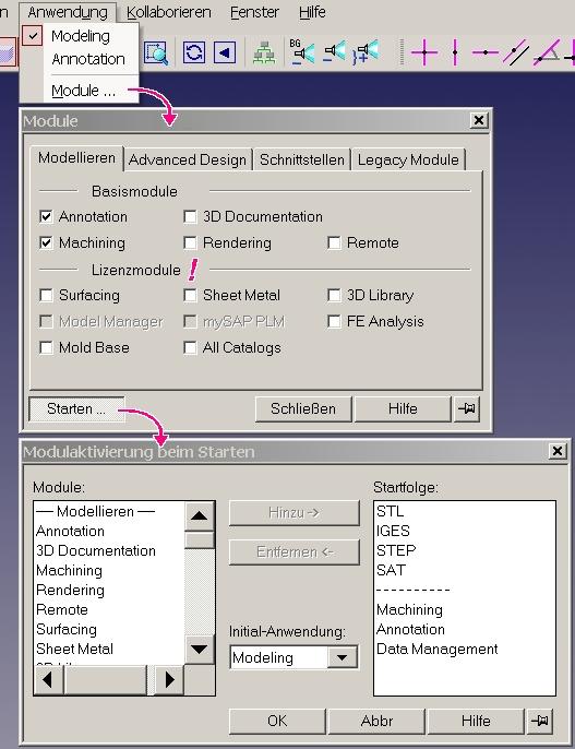
Since version 14 is this directly adjustable in the SolidDesigner program.
At Application an then Modules... a comfortable menu rises to switch on or off modules and licences.
<picture>
After tabbing Start... a new window opens to write some modules into the startup file.
Attention: some modules need licences which then are always used by you and closed for your colleagues.
Show memory for SolidDesigner
Put this into the command line
(display (/ (seventh (multiple-value-list (memory-usage))) 1024 1024))
and see how much Mbyte the SolidDesigner can use.
Change memory for SolidDesigner
Put this into the command line
(memory-limit :data XYZ)
for setting how many Mbyte the SolidDesigner can use. XYZ is the memory limit in Mbyte.
Attention: only for experienced users !
Repair damaged thread
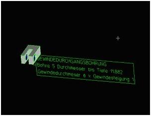
Sometimes a threat is damaged e.g. by milling in two parts. Then the threat line will in Annotation not be shown properly.
With the tool thread_func.lsp (march 2004) ) a threat can be repaired and the missing lines in Annotation are created right.
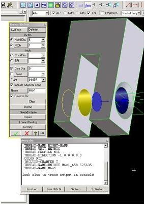
- Click on zylindrical face of the proper threat part
- Click on Ask Threat, window shows threat
- Click on cylindrical face of the damaged threat part
- Use and ok
- Update Annotation Views
SolidLibrary threat changing to machining part
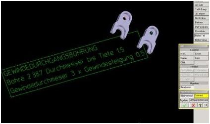
- Open SolidLibrary and activate the Machining-Tool
- 3D Library
- Library Part
- Migration
- Machine Features
Annotation - Update on another PC
Tip from Dagmar StolpmannThe updating of big drawings often costs a lot of time. It can be transferred to another computer to keep on working with the own station.
You need one or more server (to calculate the update), a dispatcher (distributes the calculation orders) and one or more clients (to deliver the calculation orders). One Computer can be server and dispatcher or client and dispatcher at the same time.
- Server: SolidDesigner has to be installed, but can be closed, only the Windows SD-server must be active.
- Dispatcher: in the installation path of SolidDesigner you find a file named binNT (Windows). There is a program StartDispatcher. Start this and enter name or network address of the server.
- Client: in SolidDesigner start the Remote module. Enter the name of the dispatcher. Now you have a new button in the standard update menu: "Local"or with "Submit" sending it to the server and with "Receive" getting it back when finished. During the calculation SolidDesigner must not be closed.
Printer clipboard in ME10
Tip from Bernard DanhieuxIn ME10 since version 11 exists a possibility to copy something to the Windows-Clipboard.
In the ME-10 printer menu the printer MSWINDOW_EMF_CLIPBOARD must be installed. The standard pen setting will be taken. It can be selected "everything" or "box". Scaling should be set to "fit". Print with OK.
Pixel picture settings have no influence.
The content of the clipboard can now be loaded in every Office-Tool with Ctrl+V for example.
Grafics are generally sized to 100x100 mm. The quality becomes better when 1:1 is nearly 100x100mm. Entering clipboard_size in the ME10 command line the size can be changed. Experiments with pen settings improve the result.
Switch between drawing sheets
Two ways are implemented:
1: Down in the status line overwrite the number of the current sheet with another (a little uncomfortable).
2: By clicking the sheet active in the drawing browser (comfortable).
I miss these buttons: "next sheet" and "previous sheet".
 So I would like to present the possibility of putting some buttons on an icon line, which allow switching directly to another drawing sheet. How to install such a button is described in Tutorials.
The code calls am_current_sheet "1" (the number is the sheet name).
Disadvantage: at drawings with very much sheets and at sheets with other names like 1, 2, 3 etc.
Locked objects getting free again
Thanks to Rolf Allenbach for compilingBy loading or partially loading from of the database sometimes it can happen that objects get the symbol "locked"
 or "untouchable"
 but it normally should be free.
An explanation of the conditions for this would be to long for this chapter. Shortly said: in an assembly are objects who have references to other not loaded objects, which sometimes causes conflicts.
Attention: first of all think about why the system could have set these lock symbols !
Often it helps to load the critical parts new.
If not coming out of the problem, it also could help to make a copy of the assembly.
But that is not very proper, when this assembly is for example used by other assemblies.
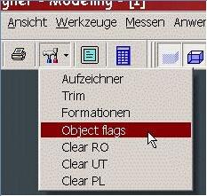
Meant for intern using, but published in serveral forums, two goodies were created to remove these lock properties.
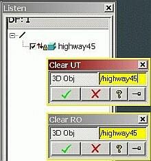 Enter to the command line (load "unlock_obj") and get two new entries in the toolbox:
Clear UT to remove Untouchables.
Clear RO to remove the padlock.
Attention: do this only when shure not to damage anything !
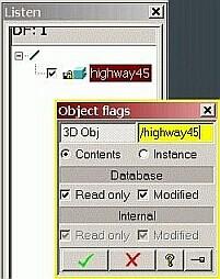 Enter to the command line (load "dbdialog") to get this entry in the toolbox:
Object flags to change the properties of a part or an assembly.
Attention: do this only when shure not to damage anything !
The English pages of osd.cad.de are currently (=Dec2017) under some re-constructions. Topics I try to attack:
- DONE On the fly translation of German-only pages, based on good progress of those translators.
- ongoing More Mobil friendly UI (at least friendly, may be not full responsive).
- DONE SEO related issues
- DONE(17/12) + ongoing check for HTML compliance (use of tidy / W3C Markup Validation Service)
- OPEN Split of some lengthy files into some sub pages (idea: about 10 chapters per page)
- ... feel free to drop me a note via the forum's private message functionality


