
Codes for 3D Modeling

SolidDesigner (aka PTC Creo Elements/Direct Modeling) can be customized in a wide and extensive area. Here are some official and some unofficial help gadgets ('codes') not saved as *.lsp or not creating a toolbox entry.
Subtopics of this page are:
01 Color tables △ ▽

- Thanks to misc
- Discussion took place at user forum on on CAD.DE.
- File to download/load is all_color.pal.
- Date created/updated is about March 2007.
This is not a lisp program but a color table for SolidDesigner. It includes 436 colors: all_color.pal (Mar 2007 - Peter Welser)
A smaller version is: meine.pal (Nov 2006)
Simply add these files to the SolidDesigner
customization directory <custdir>/palettes/.... The file extension '.pal' is needed.
After (re)starting SolidDesigner the different palettes
appear in the color selector automatically whenever a color has to be specified.
As usual administrators will add the pal files to the site resp. corp customization directory structure.
Further information in these external links:
02 Formations △ ▽

- Thanks to misc
- Discussion took place at user forum on on CAD.DE.
- File to download/load is all_color.pal.
- Date created/updated is about March 2007.
Since version 14 formations are replaced by "Configurations". To convert formations into configurations the 'Convert' command within the 'Configuration' section of the 'Part / Assy' menu. will help.
A good tool to create exploded views in SolidDesigner versions up to 13.xx is
(load "sd_form") (enter in command line or add to sd_customize).
To send the exploded views to Annotation you need
(load "am_form") (enter in command line or add to am_customize).
And here is a short tutorial how it works in rather old versions of SolidDesigner.
03 Properties of parts and surfaces + Reset △ ▽

- With friendly greetings from CoCreate.
- This is a build in goody of SolidDesigner.
- Date created/updated is about March 2007.
Part and surface properties can set or copied with this goody very comfortable in elder versions
where the property menus with the 'copy from' / 'copy to' is not available.
There are also some other interesting functions to find.
Enter (load "prop_menu")
in the command line or add the load command to sd_customize file makes the new button "Properties" available in the toolbox.
In V14 the functions are only for base properties not for instance settings.
Reset Part
- Thanks to der_Wolfgang
- Discussion took place at user forum on on CAD.DE.
- File to download/load is sd_reset_part_props.lsp.
- Date created/updated is about June 2007.
To free a part from all its properties assigned use sd_reset_part_props.lsp. The model looses all base and instance properties.
04 Thicken Menu △ ▽

- With friendly greetings from CoCreate.
- This is a build in goody of SolidDesigner.
The build in goody (load "cv3d_thicken")
can entered in the command line or added to sd_customize file makes a solid part from 3D wire lines.
A surfacing license is required
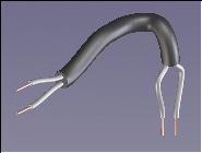
Without taking work planes can be created cables or hoses or tubes.
Some information about Surfacing functions without the need for a license can be found in Instructions.
05 2D drawing without Annotation △ ▽

- With friendly greetings from CoCreate.
- This is a build in goody of SolidDesigner.
This build in goody enables complete 2D drawings with the old layout mechanism.
Enter (show-layout) in the command line or
add this command to sd_customize to get the menu "Layout".
Advantage: the update is faster than in Annotation, damaged parts and collisions are not considered, good for short time prints.
Disadvantage: no full associative to 3D part, no threads, no sections, no cutaways, no symmetry and center lines, no shaded views etc. etc. etc. etc!
06 Delete undo memory △ ▽

- With friendly greetings from CoCreate.
- This is a build in goody of SolidDesigner.
- Date created/updated is about May 2003.
The file del_undo.dll (May 2003 V11)
deletes the complete undo memory (add it like loading lisp file into sd_customize or am_customize).
Does only work until version 11.
Makes sense after big operations or when loading big assemblies.
A much more, simple way is to enter the following command as needed:
(undo :max_back 1) as discussed on cad.de, in addition independent from the version in use.
See also Tips'n Tricks for further information.
07 Clean up the Toolbox △ ▽

- Thanks to Walter+Geppert
- More information here.
- File to download/load is menu_beispiel.lsp.
- Date created/updated is about May 2004.
You Toolbox is full of lisps and goodies and you would like to have it a little more structured?
Then the menu definition in menu_beispiel.lsp will help. You get a new button which includes all the tools in a new menu and you can sort them as you like to.
But there are several settings to be done until it looks like the picture on the right:
The file has to be filled with the start / loading commands of all the tools to make them work.
It is a good idea to have a separate menu for all the Annotation tools.
08 Recorder files △ ▽

- With friendly greetings from CoCreate.
- This is a build in goody of SolidDesigner.
After entering (load "recorder")
the toolbox includes the so called "Recorder".
It saves all following actions done for repeating them later. The files are saved as *.rec.
- After activating "Recording" - "Start" all following actions done in SolidDesigner will be recorded
- until pressing "Recording" - "Stop"
- With "Playback" - "Start" the recorder file plays back the recorded command sequence
To get a good re-playable recorded sequence here are some tips:
- Select objects by name using the structure browser (or the command line) rather than click in the view port
- Try to enter coordinates in the command line rather than click in the view port
- Avoid intensive panning and zooming (it will fill the recorder file with a lot of commands)
Using the recorder is a good starting point for writing your own actions / commands. So during recording for these purpose some more tips might be helpful:
- re-enter pre-filled options (e.g. extrude direction) to get these values recorded
- use funny coordinates like 42,42 or 1,1,1 2,2,2 or 1,22,33 so you can find them easier when transferring recorded sequence to your lisp code
- Use 'speaking' names for new objects so you can find them easier when transferring recorded sequence to your lisp code
- Enter (pprint "Now we are doing..") to get some on the fly comments into your recorder file for better orientation
- Be aware that the part current during recording is not mandatory the one being current later on
- Be aware that the work plane current during recording is not mandatory the one being current later on
A discussion about recording took place a a while ago on cad.de.
Next you see three examples how data from other (non CAD) systems can be used to create parts:
To download click it with right mouse button and choose "save link target as". After that, open it and write your coordinates over the sample coordinates.

Creates a wire frame consisting of circular curves. Every single curve is defined by start, end and radius point.
The coordinates have to be written in that specified order and in this format 0.00,0.00,0.00 (without blanks).
Creates a workplane including the spline, defined by the coordinate points.
The X Y coordinates have to be written in this format: 0.00,0.00 (without blanks).

Creates a 3D line in form of a spline. Every 3D coordinate is a spline leading point. Tangential relativities are not able to defined by this.
The coordinates have to be written in this format: 0.00,0.00,0.00 (without blanks).
See also Lisp_3D#16
License Free PE-Version
The license free PE Version, aka PTC Creo Elements/Direct Modeling Express x.y, does not have the goody 'recorder'. But there are workarounds for recording a sequence.
- For recording
- you can start adding a 'available command' for your toolbars. Inside that you can record any command sequence.
The recorded command sequence is visible when creating / editing the available command.
You can copy and paste its content into a plain text file (may be using UTF-8 character encoding)
and store it as
*.recor*.lsp. - For play back
- Simple drag and drop the file into the view port. The file will be simple loaded as lisp file and the recorded commands will be evaluated as when entering them step by step into the command line.
For creating a kind of lisp skeleton of a command used interactive this work around is doing fine on PE Version.
09 More Object Properties in Structure Browser △ ▽

- Thanks to holt
- Discussion took place at user forum on on CAD.DE.
- File to download/load is custom_browser_views.lsp.
- Date created/updated is about May 2007.
Starting with SolidDesigner Version 14 the structure browser can offer different kind of views. Those view can be user customized (with the help of some lines of lisp). That way a view with some more columns can be created displaying more properties of the objects displayed in the structure browser.
By loading the attached file a new view will be added (visible at the upper right corner of the structure browser. In the new view there are new columns for density, geometry resolution and type of part (solid/face/wire-part). That way you get a better overview and the values can be edited as well.
Be aware that inquiring more information of each and every object might slow down the performance of the structure browser since the data is retrieved on the fly (even when CoCreate implemented some caching algorithm here as well).
Its a good idea to switch back to the "Standard" view for normal working.
The English pages of osd.cad.de are currently (=Dec2017) under some re-constructions. Topics I try to attack:
- DONE On the fly translation of German-only pages, based on good progress of those translators.
- ongoing More Mobil friendly UI (at least friendly, may be not full responsive).
- DONE SEO related issues
- DONE(17/12) + ongoing check for HTML compliance (use of tidy / W3C Markup Validation Service)
- OPEN Split of some lengthy files into some sub pages (idea: about 10 chapters per page)
- ... feel free to drop me a note via the forum's private message functionality


